-
Posts
6,221 -
Joined
-
Last visited
-
Days Won
40
Content Type
Profiles
Forums
Gallery
Everything posted by sherman
-
-
Base on the earlier writeup about light spectrum and the short coming of using individual led and what to take note when using multi chip leds to overcome the disco effect of individual led in aquarium light manufacturers has come up with the latest led array for the next generation led light for reef aquariumBelow are 3 of the best known on market today. This does not include led aquarium light manufacturers like AI, Radion and Kessil, etc
-
That is why I do not encourage the addition of green light
-
Lately many manufacturers of LED fixtures have also been including green LEDs in their products. We believe that this is an unnecessary option. First of all, the true green spectrum, in the 530-560nm range, is already present in sufficient amounts in the spectrum of white LED, and therefore a separate green LED is not required on the assembly. Another disadvantage of using separate green LEDs is that so far the efficiency of commercially available green LEDs is extremely low and, to make their addition meaningful, a significant number would be required (even though the human eye is most sensitive to green spectrum), and this will affect negatively the overall heat generation by the assembly. We believe that adding just a few green LEDs to the assembly, like most manufacturers do, is a tribute to fashion and does not have any noticeable impact on the aggregated spectrum of the fixture.
-
We believe that cool-white LEDs with 6000-8000K CCT are best suited for the LED assembly to be used on a reef tank.The next color that is worth having, in order to better fill the gap in white LEDs spectrum, is cyan, or turquois, with wavelengths around 510nm.
-
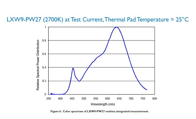
Fig 6b) Radiation spectrum of LXW9-PW27 (2700K) Warm-White emitter at Test Current, Thermal Pad Temperature = 25C
-
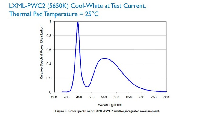
Fig 6a) Radiation spectrum of LXML-PWC2 (5650K) Cool-White emitter at Test Current, Thermal Pad Temperature = 25C
-
The next important component of the assembly are white LEDsWhite LEDs are readily available for a moderate cost, even when the most efficient bins are requested.Spectral distribution of light emitted by a cool-white emitter LXML-PWC2 (by Philips) is shown in Fig 6 (a), and a warm-white emitter LXW9-PW27 in Fig 6 (b) below:
-
Spectral considerationsWe have pointed out the importance of violet spectrum multiple times. Beside the high photosynthetic activity, this spectrum provides strong fluorescence and at the same time, it is very poorly visible to the human eye. We have also shown that, in natural sunlight, the amount of radiation in this part of the spectrum is significant. Therefore we install on our assembly several true violet LEDs with different wavelengths, covering the 400 to 430nm range. Spectral differences between these LEDs are hardly visible to the eye, and therefore we combine them all in one chain, without the possibility of individually controlling each sub-range.Unfortunately, high quality and efficient violet LEDs are still very expensive and in fact, if installed in sufficient quantity, they account for most part of the LED assembly’s overall cost Quality bin LED below 420 nm is very expensive. Range anything from USD 30 to USD 400 per piece
-
Challenge number three: Filling up the spectrum Below, we shall consider the general rules which we believe are important when designing a LED assembly, pointing out the problems and solutions that we had found in the process.We believe that only the best (most efficient) bins are suitable for making the LED assemblyAt the same time, higher conversion efficiency means less heat generation, which is also a significant factor, especially within a LED fixture’s confined space. If not specified otherwise, we always use the most efficient LED bins that are available in commercial quantities at the time of manufacture
-
Tomorrow we go to challenge number 3. Filling up the spectrum
-
Is your multi chip led array using this technology?
-
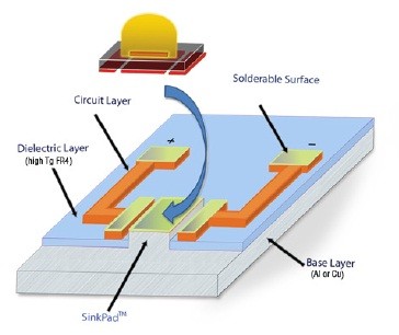
You can see the raised portions of the МСРСВ metal in the picture, which touch the LED’s thermal pad directly; whereas, the electric traces are situated on a separate PCB. This approach results in a significant reduction of thermal resistance, and the more LEDs there are on the MCPCB surface, the more pronounced is the effect. Therefore, this technology is preferred for our МСРСВ which will be densely populated with power LEDs.
-
-
In 2011, however, a US company SinkPAD (www.sinkpad.com) has offered a patented technology called SinkPADTM, allowing it to dissipate the heat from LEDs thermal pad directly to МСРСВ’s metal.
-
As we have seen, there are two main obstacles to removing excess heat from the LED crystal: the LED package and the MCPCB. Manufacturers are constantly working to overcome the first obstacle and the best LEDs on the market are using packages with reduced thermal resistance. Overcoming the second obstacle is more of a challenge since, until recently, there was no technology that would allow engineers to get rid of the dielectric layer between the LED thermal pad and the МСРСВ metal.
-
Many manufacturers avoid indicating this parameter in their datasheets, just because the figure is even worse. Also note that real-life temperatures will be worse than we calculated above, because of mounting imperfections of the МСРСВ, an uneven layer of the heat conductive compound, etc.
-
This explain why some led switch off or blink after running
-
The МСРСВ is not a part of the heatsink and is attached to it through a layer of heat conducting compound, which is required to fill in the gaps resulting from manufacturing imperfections of the attaching surfaces. The compound’s thermal resistance depends on material but, in any case, the thinner is the layer, the less will be the resistance. As a rough approximation, for a high-quality compound it is around 2C/W. This will add 4.6С and 5С respectively to our crystals.Once the heat from the LED has reached the heatsink, it cannot be instantly transferred to the environment. A heatsink is usually selected in such a way that its average temperature would not exceed 50C when the surrounding air temperature is 25C. Heatsink temperature at the contact point with the МСРСВ will be around 60C. Thus, the crystals temperature will be 60+10.1+11.5+4.5=86.1С and 60+37.5+12.25+5=114.75С respectively. Note that if we attach such LEDs to a cheap FR-4 PCB with thermal resistance about 60C/W, crystal temperature may reach 252С. Since LEDs are attached with a solder which melts at about 217С, the LED would probably unsolder due to its own heat!
-
Since we are planning to pack the LEDs tightly, in order to avoid the “Disco” effect, we shall assume a larger figure, towards 5C/W. This will add another 11.5С to 12.25С to the temperature of our crystals. These calculations are valid for a traditional MCPCB, but we can improve the situation significantly by using an advanced MCPCB like SinkPAD or similar.
-
-
Let us consider the influence of thermal resistance on crystal temperature. Suppose we have two 3W LEDs of the latest-generation. Let us consider, for example, a violet LED Semileds N35L-U-A with a thermal resistance of 4.4C/W, and a Cree XP-E2 green LED with 15C/W thermal resistance. When operating at 700mA, the respective voltage drop will be, approximately, 3.3V and 3.5V, and hence their overall power consumption will be around 2.31W and 2.45W respectively. In the first case, the LED package will add 2.31*4.4=10.16С to crystal temperature, and in the second case the temperature difference is much higher: 2.45*15=36.75С.We need to supply current to the LED and the conductors should be somehow isolated from the heatsink. Therefore, the LED emitter is first installed onto a special PCB, which is then mounted on the heatsink. Thermal resistance of least expensive PCBs can be as high as 60C/W or more (see the datasheet for Cree XLamp _PCB_Thermal.pdf). This, however, is quite unacceptable, and therefore special metal PCBs (МСРСВs) have been developed.
-
Unfortunately, commonly known technologies today do not permit mounting the LED crystal directly on the heatsink. The crystal requires a special package, and its heat transferring capability is described by a parameter called thermal resistance, usually measured in the degrees of temperature increase per watt of generated heat (C/W). The thermal resistance of the best individual LEDs is about 2.5C/W today.


