desm0nds
Newbie 1-
Posts
43 -
Joined
-
Last visited
Content Type
Profiles
Forums
Gallery
Everything posted by desm0nds
-
Thanks guys for the info. So if I am keeping tangs and live rock only in a 4-ft tank, depth is 65cm, what would you recommend for lighting? I do not have chiller nor fan. But have got a DIY internal overflow box. What would the costing be like?
-
Thanks Vel. But I think I have mislead you guys with my words when I used single-ended and double-ended. Actually what I meant was the terminal pins of the tube terminate at a single end of at a double end. So does T5 tube terminate at one end with 4 pins?
-
Hi all out there, Appreciate if you could help in answering my few queries on lighting. 1) Does T5 light tube comes in both single-ended and doubled-ended tube? 2) How much would it cost for these 2 tubes (10000k)? 3) For single ended tube, can you refer me to a correct schematic wiring diagram for a proper setup? 4) Is T5 belonging to the florescent tube family? i.e T5 is FL only difference in diameter? 5) Does MH tube comes in double ended form? 6) What is the typical cost of a MH? 7) Like-wise, any wiring diagram that I can refer to? Thanks in advance. Desm0nds
-
Mid-tank or bottom intake overflow system
desm0nds replied to desm0nds's topic in New to the Marine Aquaria Hobby
This is what I meant by not able to achieve a perfect balance. I too used to make the adjustment every alternate day. Very sianz... That's why decided to use only surface intake. But create another problem as mentioned earlier. If water is not being suck into from the surface, surely there will be oil built up sooner or later. As I have tried using only the mid-tank intake, weeks after, i can see a layer of oil on the surface. You might want to reconsider on your design? -
Mid-tank or bottom intake overflow system
desm0nds replied to desm0nds's topic in New to the Marine Aquaria Hobby
Hi guys, thanks for all the suggestion and comments. Well seems like we can't come to any conclusion yet. Currently this is what I have been using in my tank. Suppose to work with both the surface skimmer and the mid-tank intank. The mid-intake proof to be very effective in ###### in the debries. But ... sigh... I can nver achieve a perfect balance between the overflow rate and the return pump rate. (despite using the ball valve to control the flow). The idea is there but in practise, it failed. And I am hoping that someone out there could at least provide an alternative solution or maybe even modified on this system. The box within the overflow box could not be used here as you can see that I do not have a "box" in this design. -
Mid-tank or bottom intake overflow system
desm0nds posted a topic in New to the Marine Aquaria Hobby
Hi everyone, Pardon me for the long story but i need to present the background story first la. I am sure that aglae on the tank's wall is rather common among us. Despite having high water flowrate, low nitrate level, strong water current, lighting intensity and exposure period controlling etc. Still, we will have aglae growing on the wall. (If there is someone who does not have this problem, please please share with us how to achieve this.) When we scrub away the aglae, the remains tend to "swim" around in the tank. It doesn't float to the surface and as a result, they doesnt get suck into a typical surface intake overflow system. Quite often, they settled down on the sandbed, rocks or even back on the wall again. End result, aglaed wall, rock and sandbed. Yucks. I am thinking if we can have a mid-tank or bottom intake, we could remove these "waste" more effectively and more efficiently? I have tried incorporating a mid-tank intank to my existing surface intake oveflow system but it doesnt work. Somehow the balancing between the pump rate and the overflow rate is being disturbed. Having a ball-valve installed to control the flowrate doesnt work either. Anyone has a mid-tank or bottom intake overflow system in your tank setup? There are a lot of surface intake overflow system design being posted here in the forum, but none is on mid-tank or bottom intake overflow system design. Surface intake overflow is good in surface skimming as well as simpler to design as balancing the overflow rate and the pump rate is achieved automatically. But what it lack here is the effectiveness of the "waste" clearance. Hope that someone out there has a solution to this... Very much appreciated. -
Hi Chipson, I have done a similar design and put it to test. I must agree with you that this design can really support a high flowrate, really impressive. As for the end cap thing, I have done two test. One with the end cap on and the other with the end cap off. Test 1: Once the flowrate starts, I removed the end cap. Flowrate still continue though the rate drop a little. Not significant though. I guess this is due to the fact of loosing "air-tight" as you have mentioned earlier. I shut off the return pump. Once the water level in the main tank falls below the surface skimmer intake, siphoning seems to stop after the minimum water level in the cylinder has reached. Water still remain in the 2 U-channel. Next, I power back on the return pump, water level in the main tank raises and start to fill to the surface skimmer intake, the cylinder get filled up and water level in the cylinder raised and siphoning restart! bravo! Test 2: I leave the end cap on. Flowrate is at its maximum. The pump is off and water level falls below the surface skimmer intake. Siphoning stop once min. water level in the cylinder is reached. This time round, gluping sound is heard. The pump is turned on, water level raises and start to fill the cylinder. Siphoning did not restart. Further inspection found that water is no longer present in the 2 U channel. The test is re-run and similar thing happened. Chipson, I guess we can deduced 1 thing. With the end cap on, it create an air-tight full siphoning environment. When the min water level is reached, water in the pipe is still being siphoned down to the sump tank. Eventually draining out the U channel. With the end cap off, a semi-siphoning is created. siphoning will break once the water level reached the U-channel level. i.e. min water level. Cos its a semi-siphoning effect, water will be trapped within the U channel. This is important as it determine whether the siphoning will restart. I have gone through this thread from the beginning once again and realised that Melvin did mentioned about removing the end cap once siphon starts. I believe this is the reason why he said so. Agreeable?
-
Chipson, if this is the case, then why would you need to have this opening in the beginning? Is there any other features? Will siphoning restart after pump recovery from failure when the cap is on/off? Have this been tested?
-
Hi chipson, What is the function for this end cap? Can I do wthout it? Will the flowrate or the siphoning path be affected then?
-
oki will explore mine more. Nope its not an Atman though.
-
file and saw it apart?! saw wat apart? the pump itself? cannot be right? i think my mistake cos my question very misleading. actually i am asking you how you remove the whole impeller out from the pump? Not how you disassemble the impeller itself.
-
How do you remove the assembly from the pump? I tried opening up mine. I can see the entire blade part but i just couldnt pull out the entrie assembly.
-
oki. got it. thks.
-
and also. Is the "blade" of the impeller is actually being replaced by the brush construction? If so, how do the water get sucks into the modified impeller and then being push back out to the main tank? All along I thought the blade works like a typical fan. When spinned, it draws air and then pushes it out through the other side cos of the slanted blade structure? This is very intersting. Care to share more about this?
-
thanks ervine. So am i I right to say that with this constriction method, you dont actually need to have an air pump to pump into the air inlet? Its the high speed movement that will eventually draws in the air from the other end of the air tube?
-
sorry guys, i am rather ignorance to this. care to explain the need for the "twisted" point? thks!
-
So that is the system. So far, its the 3rd day of test. No sign of sump overflow or tank overflow still. I read somewhere that with the sump, the water temperature should falls 1 degree celsius lower than before. But its not true for my case leh. Still the same as before at 31. Rather on the high end right? sigh... I should starting looking at the DIY chiller thread...
-
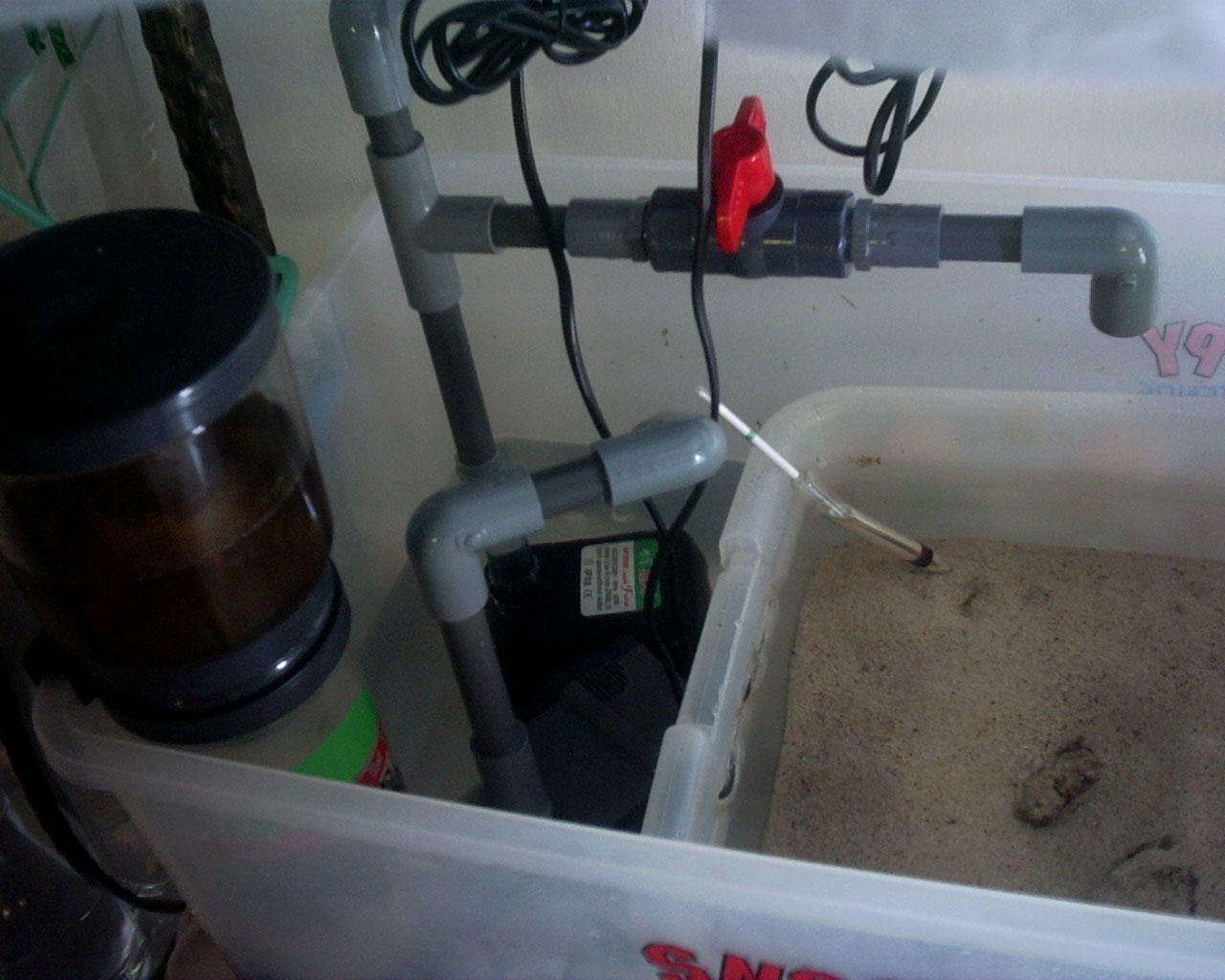
The water will go by the sand bed and to the return pump. There is a ball valve in the return pump path to work as a bleed path in case the pump rate is faster than the siphoning rate. Currently, it is closed for max. return pump power to main tank. The siphoning rate instead has to be opened 3/4 wide to keep the system balance.
-
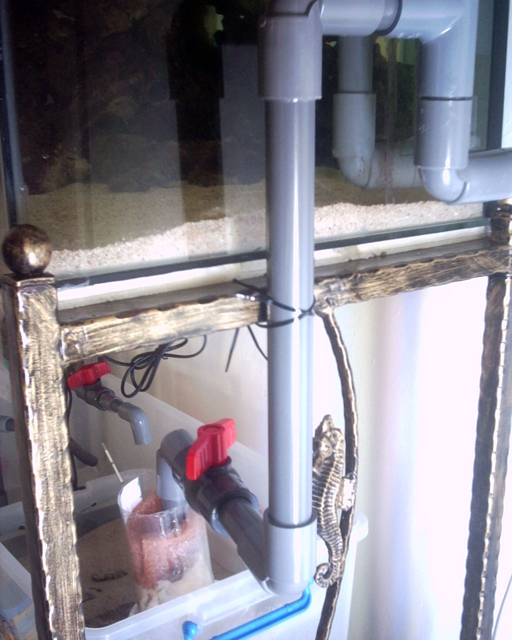
The output will eventually lead to a ball valve before it gets into the Marinda Strawberry plastic bottle "filter" compartment.
-
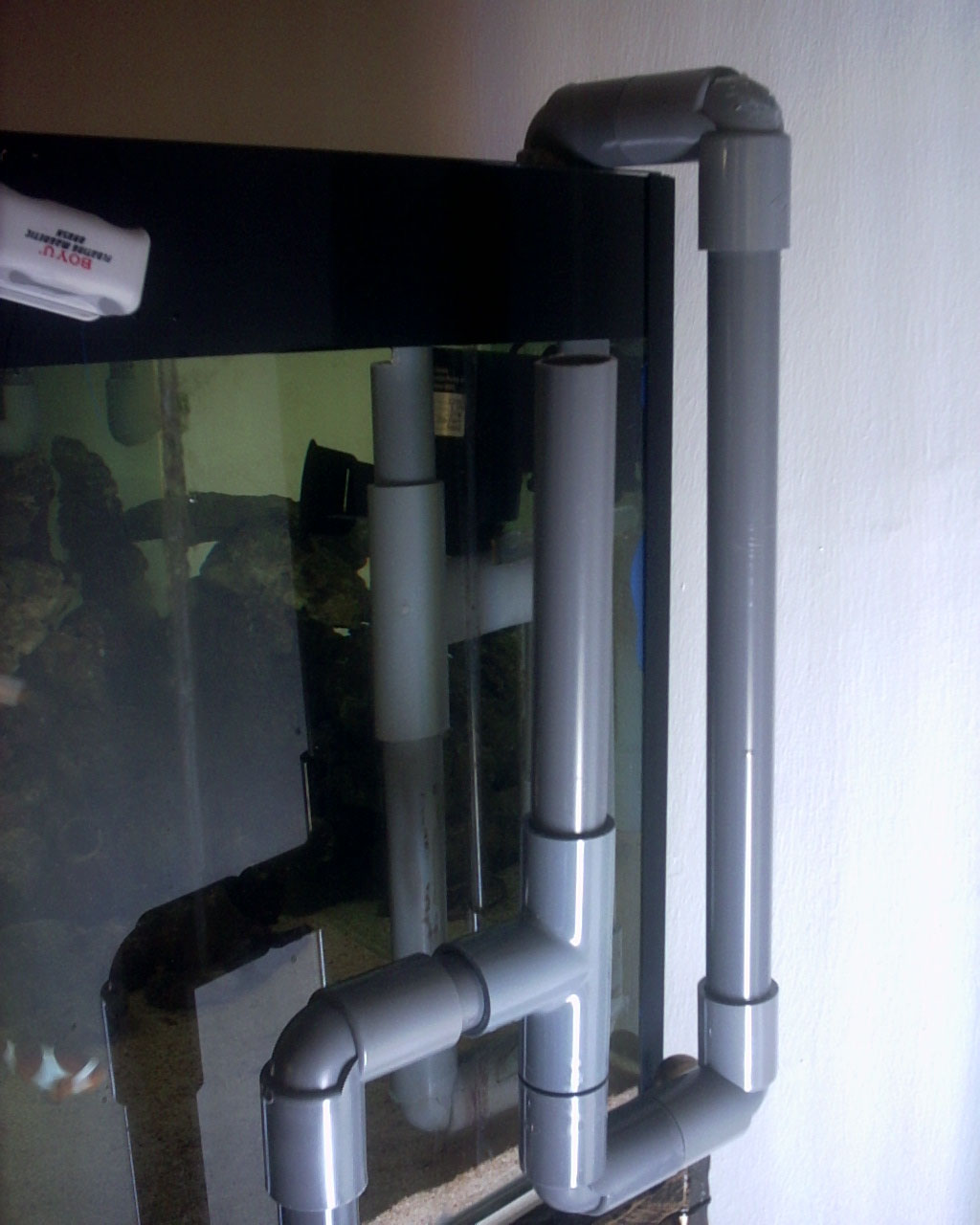
followed by the double U channel outside. For this part, I copied the design posted in the this forum and also from rockfish.
-
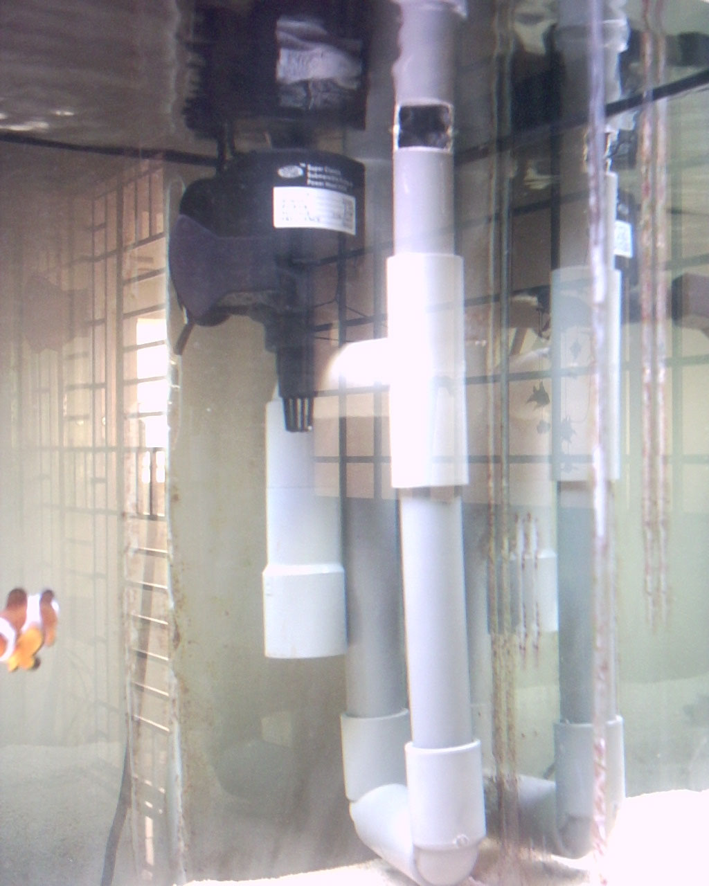
Thanks Rockfish. The design is cool but I am already in the mist of building mine. As mentioned before, I will make use of your design on my other fren's tank which are more clutter which don't require a bottom intake. Mine is very empty so a bottom intake and a surface skimmer is necessary. Ok now for the judgement day. I have completed the overflow and put on real live test on my 3ft tank. Result so far so good. Waterflow rate is matching with my 2500l/hr return pump. Both surface skimmer and bottom intake are doing their job well. I have attached some pictures. Any comment from you expert out there? Here is the first picture. The intakes.
-
Thanks Eric. No doubt I-box is the solution, what it lacks here is the fun and the satisfaction. Its the DIY thing lor if you get what I mean. Different people could have different view and there's no doubt about that. Anyway, how much does that I~box cost? :-P
-
Porc, maybe I should not say dropped below siphon break pt 1. Rather, I should say dropped till siphon break pt 1. ie. minimum water level in tank. You agree on this? Btw, apologies for distracting you from you work. :-P As for the previous design, you are right about that when u guess that I had aborted the test before my main tank get overflow. But really lor, the flowrate is really really very slow. The water is just about 3 cm away from the very edge of the main tank before.....
-
-
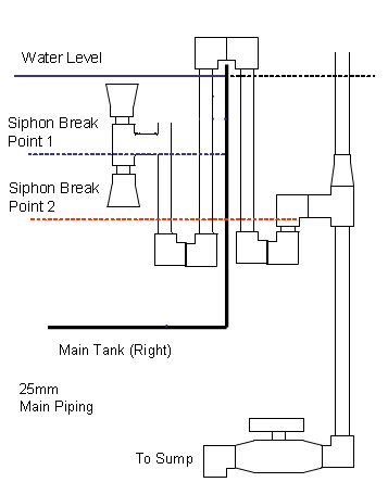
Hi guys. I am back. I have followed exactly the modified design earlier and the result..... The flow rate is indeed just to slow. Apparantly when the 2nd U is lowered, the flow rate increased. As mentioned in another thread by someone else, the column between L1 nad L2 is just too little and thus the pressure required to push the water up the last U and down to the valve. But if I lowered the U channel in order to achieve a higher flowrate, my minimun water level will be very low and I would need a huge capacity sump tank to contain the over flow should the pump failed. But it is not hopeless yet. I have came up with another design. Double siphoning breaking system. This method will allow a fast flow with the U channel lowered and yet have a higher minimum water level. Refer to the diagram. During normal operation when water level level is way above siphon break point 1. There is a full siphon in the main tank to the pipe. Water flow rate will be fast due to the outside the tank being low. The pressure in the water level difference will be enuogh to create a fast flow. And the theory of what goes in must come out still works. When water level falls to Siphon break point 1, the siphoning from the main tank water into the pipe will break. Whe this happened, water level in pipe will be undergoing a mini-siphon break when the water level in the pipe decrease further. The water level will be trapped at siphon break point 2. When water level in main tank raises way above siphonin break point 1, siphoning from main tank into pipe continues on. Hooray!


