My DPDT ice cube relays arrived and so I've been wiring them up so I can control my 220V equipment on the 120V power bar. I would like to preempt my DIY description by saying that I'm not an electrician and I don't know anything about wiring or electricity. Working with 220V power is dangerous and if you want to do this, you should get someone to help you with much more experience than I have. Also, I always use GFCI outlets as an extra measure to help prevent shock around my tanks.
That being said, this is what I did:
I am planning to use three relays:
1. Return Pump & Skimmer (on the same relay)
2. Backup Chiller
3. T5 Lights
I ordered 120V DPDT (Double Pole Double Throw) ice cube relays with sockets for wiring them up: http://sg.mouser.com/Search/ProductDetail.aspx?qs=h3Xc2LqAealUHVBqYsNmcw%3D%3D http://sg.mouser.com/ProductDetail/Magnecraft-Schneider-Electric/70-459-1/?qs=%2fha2pyFaduhd44dwsOGTU1ZXsrWMkUAcnzbpuLblr4M%3d
These will allow me to turn on and off 220V devices using the 120V APEX Powerbar without buying 120V devices and converting power from 120V to 220V.
Instead of trying to explain how to wire them up and how they work, I figured I would just post a link to this site: http://www.learningaboutelectronics.com/Articles/How-to-connect-a-double-pole-double-throw-relay-in-a-circuit
1. Return Pump & Skimmer
I will use the 1st relay for the pump and skimmer so I can program a feed mode that turns off all water flow. I am turning off the skimmer at the same time as the return pump because I don't want the skimmer to overflow when the water level rises from turning off the return pump.
I plan to only use 6 of the 8 terminals on the relay. I've decided to use the NC terminals for the skimmer & pump instead of the NO terminals. The NC (normally closed) terminals are activated when is there is no power. This means that if something goes wrong with controller and it loses power, the circuits will fail open. It might seem a bit counter intuitive, but when I want to turn off the pump, I will need to turn on the Apex outlet connected to the relay. So, as part of the Apex feed mode, I will program it to turn on the power outlet connected to the return pump & skimmer relay when the feed mode is activated.
The connections from the main power supply go to the COM (or Common)
Here is how I am connecting the DPDT relay for the return pump & skimmer:
Terminal # / Wire
13 / 120v positive (Coil)
14 / 120v negative (Coil)
9 / 220v positive from wall (COM+)
12 / 220v negative from wall (COM-)
5 / not used (NO+)
8 / not used (NO-)
1 / 220v positive from the pump (NC+)
4 / 220v negative from the pump (NC-)
The 2nd and 3rd relays are for the backup chiller and the T5s, I will use the NO (Normally Open) terminals because I want the circuit to fail closed. If there are any issues, I want to lights and backup chiller to remain off. Everything else remains the same.
5 / 220v positive from the appliance (NO+)
8 / 220v negative from the pump (NO-)
1 / not used (NC+)
4 / not used (NC-)
I've tested the first relay and it works fine. Without any 120V power, the outlets are on. When I turn on the 120V power, the outlets turn off. Each relay can handle 15A, which is way more than I need. I still need to find a suitable enclosure for the relay so they don't have the power terminals exposed.
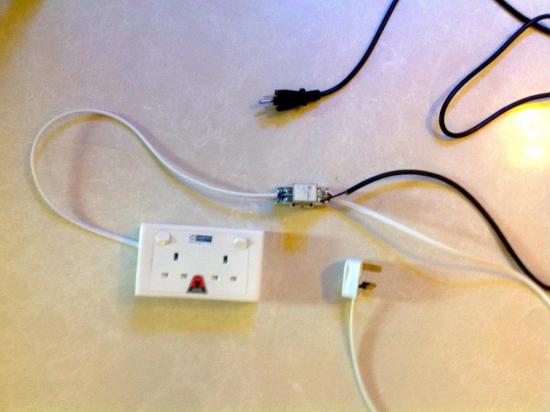
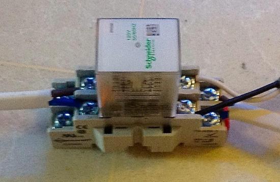
Here are some blurry photos of the finished product.:


